
Robot assembly
Overview
Body shape
To obtain a prototype that can move efficiently in liquid, low drag and stability are design priorities. While deciding the shape of robot, we referred to the design of ships since they are hydrodynamically efficient bodies confirmed by centuries of engineering experiences. The shape of the ship hull has significant impact on the resistance and stability of the ship and also our prototype.
Monohull and multihull are two possible configurations. Monohull refers to the profile with only one hull, whereas for multihull the boat has more than one hull (See Figure 4-3). Multihull configuration can be classified by the number of hulls [2], and catamaran is one of the the multihull configurations with two symmetric hulls.
Figure 4-3 right shows the structure of the Catamaran configuration. It consists of two ship hulls and a bridge deck to carry loads stably.Catamaran configuration was selected as our choice since its has a wide span which promotes stability so that the electronic components placed on the bridge deck are unlikely to get wet and be damaged. Catamaron is also more stable than monohull due to less degree of heeling [2]. In addition, the contact area of catamaran ships with the liquid is smaller than monohull when the same payload is considered [2]. The smaller the contact area, the smaller the friction drag that is imposed on the body during motion at the liquid surface. Thus, we can possibly achieve higher acceleration given the same propulsive force by the actuators.
Exploring different body shapes.....
Before the team had decided to work with floating robots, we also attempted entirely sealed underwater robot design. Through the process, we realized it was difficult to create a light weight waterproof body that was convenient to be re-opened all the times for us to inspect electronic faults. Due to the time constraint, we didn't complete a fully underwater robot but worked with a floating one which is easier to fabricate and fix.
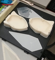
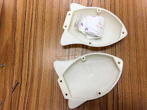
Below shows two preliminary versions of underwater robot casing, one mimicking a fish and the other mimicking a ray. Screws and nuts were used to combine different 3D-pinted body parts together.
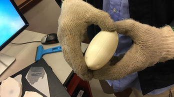
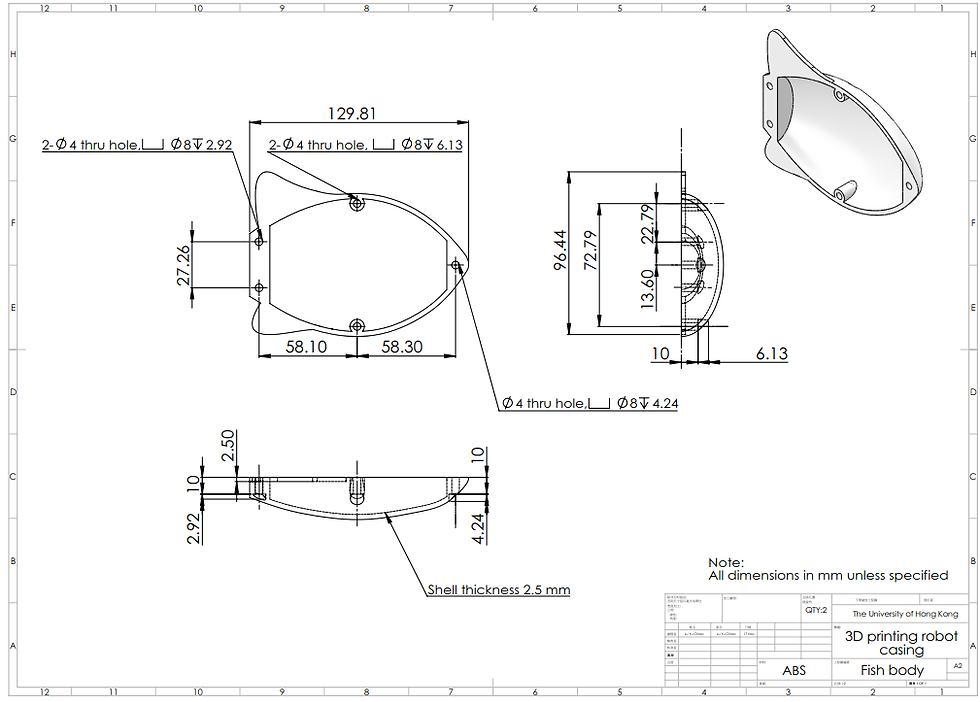
1. Fish design
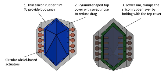
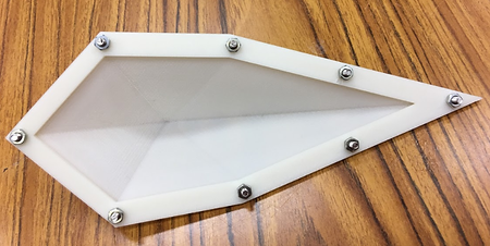
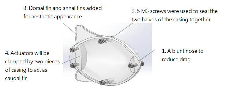
The ray model consisted of a top, pyramid-shaped cap and a screw skirt beneath, sandwiching a silicon rubber. The actuators are clamped between the cap and the skirt using screws, and the silicon rubber sheet that is also clamped in between creates a watertight space between the cap and skirt. The model could be conveniently assembled or dissembled for regular replacement of the actuators or inspection on the electronics. Note that in the photos below the silicon rubber layer was not fabricated and thus not included in the assembly.

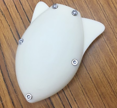
The above two models were not used eventually because liquid will leak into the interior of the shell, which may cause damage to the electronic components stored inside. We arrived at this conclusion by conducting a simple test. We dropped the assembled fish model (its interior stuffed with dry tissue paper) into a water tank and left over night. The paper tissues were wet the next day we opened up the fish casing, and therefore we concluded that using mere screws and nuts are insufficient for creating a watertight body.
3. Waterproof issues
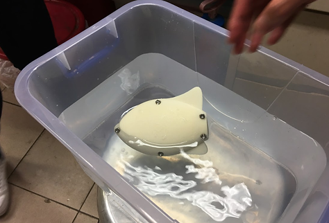

Tissue inside the fish found wet after soaking the fish in the tank for 1 minute
Describe your image.
Describe your image.
2. Stingray design

Figure 4-3. Monohull and Multihull Catamaran configurations of boat

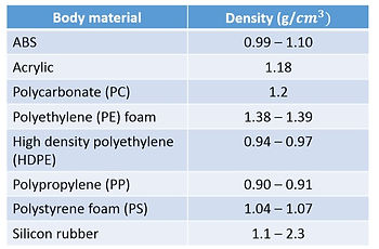
From the selection matrix, styrofoam was chosen as the body material since it has the lowest density and weight. In addition, it is the most craftable material among all 3 options.
References:
[1] Chu WS, Lee KT, Song SH, Han MW, Lee JY, Kim HS, Kim MS, Park YJ, Cho KJ, and Ahn SH. 2012. Review of Biomimetic Underwater Robots UsingSmart Actuators. International Journal of Precision Engineering And Manufacturing, 13(7) :1281-1292
[2] Dubrovsky V. Ships with Outriggers.2004. Backbone Publishing Co.
Body materials
Some low density, easily accessible materials that could possibly be used to fabricate robot body are listed in the table below.
To make the prototype move efficiently at liquid surface, the material of the body has to meet 5 requirements, which are low density, waterproof, rigid, craftable and light.
(i) Low Density
The density of the body must be lower than or close to the density of the liquid medium, so that the body can have sufficient buoyant force to stay afloat at the liquid surface.
(ii) Waterproof
The material must be anti-corrosive in alkaline electrolytes, such as the robot body would not be corroded by the electrolyte (1 M/mole NaOH) and form gaps through which the electrolyte might leak into the interior of body and damage the electronics.
(iii) Rigid
The robot body is also going to be used as cavity to bear the weight of all the electronic components and the battery, so the body has to be rigid enough to bear ~ 50g without deforming. As the prototype will not undergo any acute impact during testing, the material does not necessarily need high strength and toughness.
(iv) Craftable
The body material must be easily handcrafted using simple tools such as cutter and sandpaper.
(iiv) Light in weight
The material has to be as light as possible to reduce the mass burden imposed on the actuators during acceleration.
Regarding the above 5 requirements, 3 materials fulfill all of them which are ABS (common 3D printing material), styrofoam (Polystyrene, PS) and Acrylic plastic (Polymethyl Methacrylate). By using the selection matrix below, the 3 materials are further accessed in order to choose the most suitable one. The scale is from 1-3, where '1' represent the least competitive option in specific requirement.
The function of the robot's body is to isolate the electronics from the wet environment, and create a platform for attaching the actuators. The body should be light-weighted and with a shape generating low drag when moving in liquid so that the resistance for acceleration is reduced. Additionally, the body must have some degrees of buoyancy to support its own weight. These requirements were integrated during robot body design through careful body shape selection, material selection, and buoyancy calculation. The assembling procedures of the robot are included at the end of this page.
The overall dimension of the body is 95mm x 78 mm x 37 mm, which is of medium size when compared to other underwater robots using smart actuators according to the work by Chu et.al. [1] Future work should focus on further reducing the robot's body dimension to increase its speed performance (in the units of body length/sec).
Buoyancy calculation
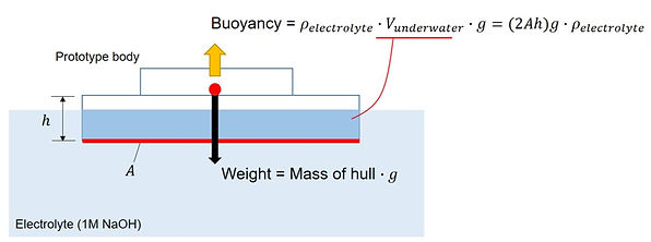
To keep the prototype stay afloat, the buoyant force has to be equivalent to the sum of weight of the robot. According to Archimedes Principle, buoyancy is equivalent to the volume submerged under the liquid surface multiplied by the density of the liquid. In our case, the submerged volume can be calculated as the projected area of the hulls multiplied by the thickness of hull immersed in liquid. The following schematic shows the free body diagram of the robot at rest.
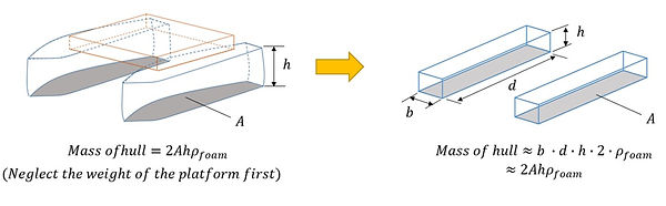
Since the plan area of the ship hull is irregular, it is difficult to estimate its volume under liquid. Hence, we approximate the hulls as cuboids by letting the width and length of the cuboid equal to the maximum width and length of the original ship hull respectively. The maximum length of the hull (denoted as 'd'), 9.5 cm, was designed to be slightly longer than the PCB so that there will be sufficient space for battery. The maximum width of both hulls were designed to be 2 cm.
The mass of the electronics, including battery, was weighted as 24.8g. The depth of the hulls, as denoted by 'h' in Figure 4-6, was determined through an iterative process illustrated below.
The total weight of the prototype is the sum of electronic's weight and body weight, where the latter depends on thickness of the hulls. As a start, we guess the total weight as any number greater than 24.8 g, say, w'. The weight of the body is thus (w' - 24.8) g, and since the density of styrofoam, width, and length of the hulls are known, we obtain an initial thickness of the hulls given by the weight w', say, denoted by h''.
On the other hand, the minimum thickness of the hull can be determined from Archimedes principle since the buoyancy of the body must be equal to the guessed total weight, w'. This minimum thickness of hull is denoted as h'. The value of h' is compared with h''. Consider two cases that are unacceptable--
(a) h' > h'': The guessed total weight is too light such that the thickness of hull is too shallow. The robot will sink due to insufficient buoyant force. Increase the guessed weight w' and repeat the calculations.
(b) h' << h'': The guessed total weight is too heavy. The thickness of the robot is far greater than that required by Archimedes principle. Reduce the guessed weight w' and repeat the calculations.
The iteration ends when h' ~ h".
After the iterations, the depth of the hulls submerged under liquid (1 M NaOH) was determined as 1.25 cm and the final weight of the prototype was 50 g. The total depth of the hulls were twice the submerged depth, which is 2.5cm for safety reasons (to prevent immediate contact of the electronics with the electrolyte in case the robot became unbalanced and inclined).
Figure 4-4. Schematic of the force balance of the floating robot
Figure 4-5. Schematic of mass estimation of twin-housed-shaped body
Assembling procedures and concerns
Figure 4-6. Final design of the twin-hull's depth

Installation of the Counter Electrode
To facilitate successful actuation, stable connection between the circuit board and counter electrode (CE, a platinum mesh) must be ensured. A short distance between the PCB and CE should be maintained to avoid tearing and loosening of the jumper wires. Since the robot is small, the distance between actuators and CE does not affect actuation rate or strain significantly. CE can therefore be placed anywhere convenient as long as it maintains good wire contact. The area of the CE, meanwhile, should be as large as possible to accelerate actuation rate.
On the other hand, frontal area of the prototype should be reduced as much as possible to decrease drag. Hence, the platinum mesh (roughly 5cm x 3 cm) is placed parallel to the ship hulls, yielding almost zero addition to frontal area of the robot. The Pt mesh is pressed into the styrofoam body and held in place by friction.
Figure 4-8. Assembly details
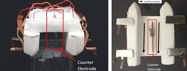
Figure 4-7. Orientation of the Counter Electrode
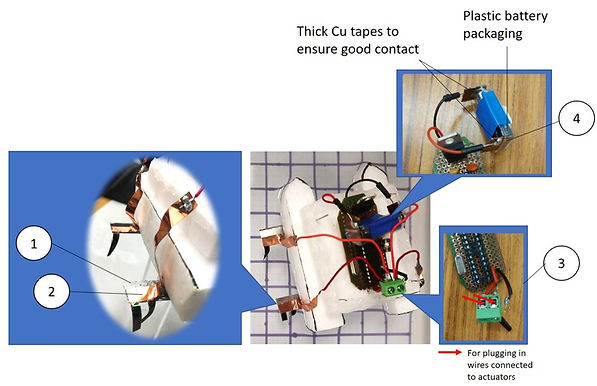
After the styrofoam body, the electronics, and the actuators were all fabricated and checked, they were assembled together as shown in the photo below. The number in the bubbles in Figure 4-6 corresponds to the following explanations.
1. Firstly, four steel base plates were attached to the bottom of the hulls using silicon rubber sealant to act as a support for the actuators. This is to prevent the propulsion of the actuators being absorbed by the swinging motion of the Cu tape.
2.Then, four sets of actuators were attached to the steel plates using silicon rubber sealant. Next, the jumper wires soldered to four Cu tapes were connected to the output ports of the PCB via a screw-tightening connector (to ensure better contact).
3. Following this, the two input power wires of the PCB are connected to the battery.
References:
1. http://www.pvc.org/en/p/specific-gravity-density
(iv)
(iii)
(ii)
(i)
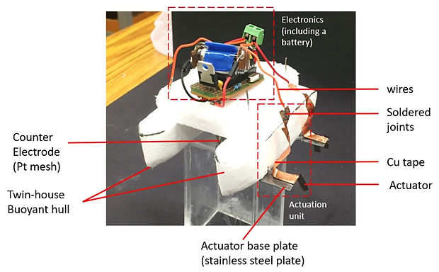
Figure 4-1. Isometric view of the assembly
Different angle views of the robot


Summary of body specifications
Figure 4-2. (i) Front view, (ii) top view, (iii) bottom view, and (v)side view of the prototype