
In this page, we have introduced the working principle and fabrication method of a Nickel hydroxide/oxyhydroxide actuator and the various factors affecting its deformation behaviour.
The current design is a rectangular strip, 2cm x 0.4cm, and exhibits the largest actuation amplitude at step voltages of +/-1.5V with a actuation frequency of 0.25Hz.
We introduced two methods to estimate the thrust force generated by a single actuator. In the first method, we integrated the drag force along the actuator to obtain an expression for drag-based actuation force, which is proportional to the square of actuator tip velocity. The actuation force evaluated at the maximum tip velocity was approximately 20 uN. In the second method, we model the aluminum strip attached to the actuator as a prismatic beam and its end-deflection is a result of net actuation force generated by the actuator.
Referring to the studies done by others, Cen and Erturk [3] achieved a 10mN actuation force with their piezoelectric ceramics composite actuato, which is four order og magnitude higher than our current estimated values. Indeed, our current estimation method of actuation force simplifies the complicated forces in 3D down to much simplified versions (such as 1D beam deflection calculation or 2D integration of drag force), and this may lead to significant underestimation of actuation force. On the other hand, there is still room for improvement in terms of the device strain and actuation stress of the Nickel hydroxide/oxyhydroxide actuator.
Material Characterization
From previous research , the Nickel hydroxide/oxyhydroxide actuator can be actuated at sub-voltage level of ~0.4V. It generates large device strain and can be fabricated into various 2D shapes (can be potentially made into shapes that are hydrodynamically efficient) which shows great potential as a compact prime-mover.
This page first briefly introduces the working principles of the Nickel hydroxide/oxyhydroxide actuator, and then moves on to the characterization work, including: the identification of working voltage range, material selection for counter electrode (CE), actuator coating time and current density, actuator shape and dimensions, and actuation frequency. Following this is the preliminary theoretical work to estimate the propulsive force of each actuator.
The actuation is accomplished in an electrochemical cell with three electrodes: the working electrode, the counter electrode, and the reference electrode, as shown in Figure 2-1. We apply an alternating potential across working electrode and the counter electrode, and the ions in the electrolyte serve as a medium to transport electrons to the surface of working electrode to close the circuit.
Nickel hydroxide/oxyhydroxide actuator -
How does it work?
Fabrication
Ni and Ni(OH)2 films are electrodeposited in sequence onto a piece of conductive glass (FTO - fluorine doped tin oxide). To make actuators into any shape we desire, a mask of 50 um-thick chemical-resistant sticker (Max Bepop, CM-200E) was cut to cover the regions that does not want to be electrodeposited. After sticking the sticker onto FTO, only unmasked regions of FTO will be coated.
The below figure is an overview of the fabrication process of the actuator.
Source of propulsion - action and reaction
Actuator design
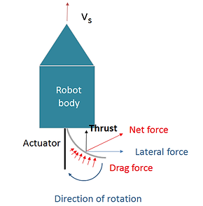
Figure 2-6. Schematic of thrust generation of the robot studied in our project
Video 1 illustrates a failure case when the actuator cannot uncurl itself when the actuator was made to a very large size of 2cm x 3 cm. Video 2 shows the actuation of a circular actuator, and its movement is significantly slower compared to the rectangular actuator in Video 1.


Figure 2-9.(a) Ineffective actuation of circular and triangular actuators, and (b) two actuation situations of wide, rectangular actuators
(a)
(b)
Video 3
Video 2


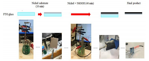
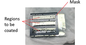
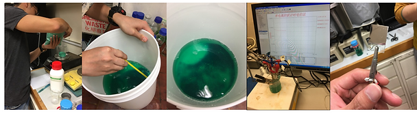

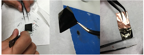

Figure 2-11. Schematic of the effect of having too thin or too thick Nickel substrate layer

3. Identifying the suitable actuation voltage range

Figure 2-12. Schematic showing the influences of different electrodes on the actuation voltage range

Figure 2-13. The Mercury-based reference electrode (left) and the schematic for potential shift when RE is removed from the electrolyte bath (right)
4. Identify the suitable actuation frequency
In the previous argument we argued that the higher the flapping frequency of the actuator, the larger the thrust it can provide to propel the robot. However, we realized that when the frequency was too high ( > 1Hz), there was insufficient time for redox reaction to take place and the actuation amplitude reduced. If we analyze the instantaneous speed of flapping in terms of the degrees rotated by the end point of the actuator (with respect to the netural axis) divided by the time taken, then increasing the actuation frequency reduces the time taken, but at the same time reduces the angular displacement of the end point. An experiment is thus required to find a better solution under this trade-off relationship.
Figure 2-16 displays the maximum instantaneous tip velocity of three distinct actuators actuated at three different frequencies. The maximum tip velocities were taken average over 5 actuation cycles and were obtained using the method illustrated in the Appendix section of this page. These three actuators had a constant width of 0.4 cm and with length of 1.5cm, 2cm, and 2.5cm respectively.
Results indicate that maximum tip velocities are highly sensitive to the geometry of actuator. Shorter actuators are capable of higher actuation frequency (0.5 Hz), while longer actuators performed better at lower frequency (0.16 Hz/0.25 Hz). This finding correlates with the fact that longer prismatic beams often have lower natural frequencies, and the deflection of the actuator itself very much simulates the bending of a prismatic beam.
Altough the data shown in Figure 2-16 contains high experimental error due to insufficient iterations, we decided to select the condition which gives the highest tip velocity according to the graph, which is 2cm x 0.4 cm actuated at 0.25 Hz.

Figure 2-16. The tip velocity of actuators of 3 different areas actuated at 3 different frequencies in 1M NaOH at +/- 1.5V
Summary of actuator development
The specifications for the actuator's qualities and actuation conditions can be summarized as below:
Auxiliary: Estimation of actuator thrust

Figure 2-14. Different CE materials tested (top) and photos showing the actuation bath of respective CE (bottom)
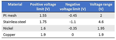

Figure 2-15. Photo of actuators immersed in different solutions (DI water, 1M sodium hydroxide, 0.13M NaSO4 (used for electroplating Ni(OH)2 layer), and in air)
Constant actuation voltage at +/- 1.5V
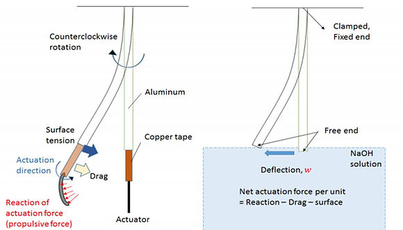
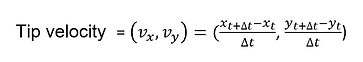
Figure 2-18. Force-body-diagram of actuator hung by a cantilever aluminum strip immersed in NaOH

1. Drag-based approach for estimating actuation force
We would make use of the drag formula:
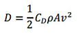
Thus, here we present the calculations of integration of drag along the actuator. Here, we simplify the actuator's motion into pure rotation of a flat plate about a pivot point. All points along the actuator would undergo the same angular velocity.
Where density of 1M NaOH: 1.04 g/ml = 1040 kg/m^3
A = 0.8 x 10 ^(-4) m^2 (for a 2cm x 0.4 cm actuator)
v = maximum tip velocity of the actuator ~ 2.5 x 10^(-2) m/s
The calculation indicates the the actuation force generated per actuator is in the scale of micro-Newtons.
Concluding comments
Appendix: Calculation of actuator tip velocity
The detailed steps for calculating the actuator tip velocity is illustrated in the following. First, an actuation video is taken from the top of the electrolyte bath with a high definition camera ((DSC-H70, Sony Co.). The video is then loaded into a motion-tracking freeware, Kinovea for analysis. The actuator tip location is tracked by manually clicking on (roughly) the end-point of the actuator and the software follow the point's movement over 5 actuation cycles. When the software fails to follow the point, the tracking cursor will be manually dragged back to end-point. The point's X and Y coordinates are recorded every 0.04 second. The resolution for video analysis is approximately between 80 and 125 um. The tracked x- and y-coordinates are in the units of image pixels. Pixels are converted to centimeter by dividing by the number of pixels equivalent to 1 cm of the graph paper that is included in the actuation video.

Figure 2-5. Photos of peeling off the actuator from FTO and attaching it to Cu tape
Figure 2-3. (i) In-progress photos for preparing the Nickel Plating Kit and the electroplating process, (ii) the electrodeposition setup, and (iii) the change in voltage over 10 minutes (with constant current desnity of -15mA/cm^2) measured by electrochemical workstation across FTO and Ni anode


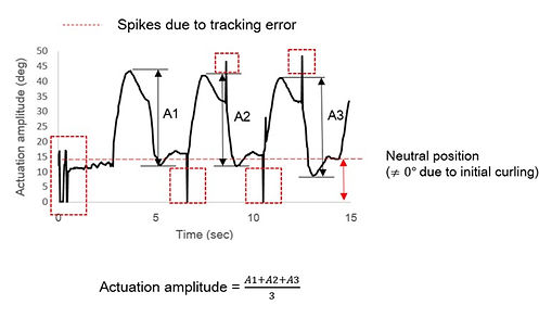

Figure 2-19. Tracking the end point of an actuator with Kinovea (left) and the time, x-, and y-coordinates are saved as Excel files (right)
The next step is to calculate tip velocity and actuation amplitude based on the Excel file data. We make use of the differential method to obtain velocity from x-and y- positions (see below). We make use of trigonometric identities to calculate the actuation amplitude - the angle made between the actuator and its neutral axis.

It could be noticed that both the tip velocity and actuation amplitude are functions of time. Plotting them on the same time axis, we obtain a graph as below:
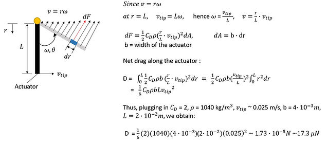
We notice a highly periodic pattern in both tip velocity and actuation amplitude. We observe two extreme values both in tip velocity and actuation amplitude, one during the forward stroke, the other during the backward stroke. There is some initial curling in the actuator at approximately 15 degrees. It could be observed that the actuation amplitude is not symmetric about the neutral position. The angular displacement in 1 cycle is 25 degree counterclockwise and only 5-10 degree clockwise. This is expected since the actuation is due to the contraction in the Nickel hydroxide/oxyhydroxide layer, which is positioned to facing right in the video. The unexpected 5 degrees to the left may be the overshoot due to inertia.
It is also noticeable that the velocity during the backward stroke is higher than the forward stroke. This finding confirms the propulsion theory proposed earlier - the reaction/drag force due to the flapping of the actuator is higher in the backward stroke resulting in a net movement forward.
Significant noises that appeared in sharp spikes could be neglected. These are tracking errors due to sudden movements of the tracking cursor as a result of the software not being able to distinguish the end-point properly. This graph only shows actuation with 3 cycles. In all the data analyzed in this project, 5 actuation cycles are always included. Break-up figures of actuation amplitude and tip velocity are further presented below:
Figure 2-20. Tip velocity and actuation amplitude plotted on the same time-axis
Figure 2-21. Break-up figures of (i) actuation amplitude and (ii) tip velocity plotted against time
(i)
(ii)
(iii)
(ii)
(i)


Figure 2-4. (i) The electroplating setup for Nickel hydroxide/oxyhydroxide, (ii) the finished look of Nickel hydroxide/oxyhydroxide coating, and (iii) the change in voltage over 40 minutes during coating process (under constant current density of 0.4mA/cm^2) measured across FTO and Pt electrode
(i)
(ii)
(iii)
Step 1:
The FTO is placed into a commercially available Ni Plating Kit (Caswell), a dark green ionic solution. A pure nickel plate is used as the anode and act as source of nickel ions during electroplating to avoid unwanted defect due to a decrease in nickel ion concentration during electroplating. By applying a constant current density of -15mA/cm2 for 10 minutes with the electrochemical workstation (LSK2006), a thin layer of Ni is coated onto the FTO. The current density is suggested by Caswell while the plating time is determined based on empirical experiences.
Step 2:
The FTO coated with Ni is then placed into another beaker containing a light green solution consisting of 0.13 M NiSO4, 0.1 M NaOAc and 0.13 M of Na2SO4. The counter electrode is a Platinum mesh (for pure electron conduction) and a Mercury-based reference electrode is added into the beaker. Note that the electrolyte is vigorously stirred throughout the plating process. A constant current density of 0.4mA/cm2. for 40 minutes with the electrochemical workstation (LSK2006), a layer of Ni thin film is coated onto the FTO. The step of stirring is highly critical since it results in a solid thin film compared to nanoporous thin film produced without stirring (see Kwan [1]). Note that both the current densities and the plating time here has significant impact on the actuator's actuation behavior which will be discussed later.
Step 3:
The thin film is peeled off from the FTO using tweezers. The same FTO were reused many times (changed after ~20 times of usage) before the coating quality deteriorates severely. In order to provide a base support for the cantilever actuator, the actuator is sandwiched between a Cu tape (3M) cut into rectangular shape. The Cu tape and the actuator forms an right angle and together they are considered as an actuation unit. Laquer is applied to lower section of the Cu tape which would be later immersed in 1 M NaOH solution. The aims is to avoid dissolution of copper and also block the alternative path for electron conduction other than the actuator's surfaces.
The actuator is a thin film consists of two layers: pure nickel substrate layer in color silver, and a top layer of nickel hydroxide in black. The nickel hydroxide layer is the main actuating layer and is approximately 10 times thicker than the substrate layer such that it is stiffer and able to deform the substrate.
When a positive voltage is applied to the actuator, Nickel hydroxide is oxidized into Nickel oxyhydroxide. This reaction is known to bring about approximately 10% volume shrinkage in actuating layer, resulting in a 'curling' up movement in the overall actuator. When negative potential is applied to the actuator, the nickel oxyhydroxide reduces and the actuator returns to its initial position. The above process is described as an actuation cycle, and this reaction is often abbreviated as 'redox' reaction (reduction-and-oxidation reaction). The fact that nickel hydroxide/oxyhydroxide are basic oxides means that this reaction can only take place in basic solutions, and in this case we selected a strong alkaline: 1 M sodium hydroxide. Theoretically, any solutions containing OH- ions would work. The following figure and video shows the actuation mechanism and actuation process of nickel hydroxide/oxyhydroxide actuator.
Since we are considering using nickel hydroxide actuator as a propeller, it would be helpful to study the basics of underwater propulsion. Here, we consider a simple case where propulsion is enabled through action-reaction principle. As the actuator flaps against water, the displaced volume of water exerts a reaction force on the actuator which pushes the micro-robot forward. The idea of this mechanism is illustrated in Figure 2-6.
It should be noted that the action-reaction principle is a simplified description of the propelling system. The actuator is not a rigid flat plate and the it is deformed by the surrounding liquid which would reduce effective propulsive force. Another point to consider is the flapping frequency: researchers have found that vortex shedding due to high frequency flapping motion produces lift force which dominates the propulsion and should be separately discussed from the action-reaction force mechanism [2]. However, our actuator actuates at a low frequency (maximum 1 Hz) range and the generation of lift force is thus not significant.
It might be useful to study what are the governing parameters for propelling force of the actuator. In fact, the reaction force mentioned earlier on, exerted by the water on the actuator, is simply the hydrodynamic drag force. The drag formula is often given as
Where Cd is the coefficient of drag, ρ is the density of the fluid, A is the frontal area normal to the direction of actuator flapping motion, and v is the velocity of the body relative to the fluid. Instinctively, Cd is related to the shape of the tail, and the tail geometry should give a high Cd. Likewise, larger tail area and tail flapping velocity would give larger drag, which is in turn converted to propelling force.
An situation one may immediately relate to is the fact that there will be drag force exerting on the thin foil no matter during forward or reverse flapping. Our hypothesis is that the drag force produced during the backward stroke (with an reaction force pointing towards the front) is higher than the forwards stroke (with an reaction force pointing towards the back) due to higher tip velocity when the actuator "bounces" back from the curved (actuated) condition back to its original position. It is with the same principle as breathstroke swimming: one produces significant thrust while sweeping the arms backward, but a slight retard in motion also occurs when the swimmer returns both of his/her arms to the front. The above description is illustrated in Figure 2-7.
We conducted experiments on comparing tip velocities of rectangular actuators with different lengths and a constant width of 0.4cm. We roughly concluded that the actuator lengths beyond 2 cm is ineffective in producing fast actuation response and should be avoided. 0.25Hz was selected as the actuation frequency for all three actuators, since this is the highest frequency that would allow all actuators to achieve its fullest displacements. The standard actuator size is then set to 2 cm x 0.4 cm.
2. Carefully selected thickness ratio between the two layer improves actuation performance.
In the introduction section we introduced that the Nickel hydroxide/oxyhydroxide layer (3-5 um) is roughly 10 times thicker than the Ni substrate (300-500nm). This ratio is achieved by 5 minutes of Nickel coating followed by 30 minutes of NiOOH coating, which was the standard practice first developed by Dr. K.W. Kwan for a standard 2 cm x 0.5 cm actuator.
What if this ratio of 10 is changed? What is the ratio giving the greatest actuation amplitude?
This ratio is is related to the coating current density and time allowed to grow each layer. Longer coating time or higher coating current would in general result in thicker layers, although the increment in thicknesses may not be linear. It is difficult to measure the thickness ratio without using electron microscope, howerver, relevant research has been carried out in characterization work by Dr.Kwan [4].
The best layer thickness ratio was decided based on naked eye observations of the actuation amplitudes. 5 different coating time combinations to electroplate the two layers were experimented. All actuators were of standard size 2cm x 0.4 cm and were actuated at +/- 1.5V, 0.16 Hz (slow enough to enable full actuation). The qualitative results are summarized below:
Through experiments, it was found out that when less time was used to electroplate the Ni-substrate layer, it was not rigid enough to support the NiOOH layer and the whole actuator curls up due to surface stress in the actuator. The curling significantly impedes actuation. Also the actuator is more likely to break apart after several actuation cycles when the Ni-substrate was coated for a shorter period of time. On the other hand, when the Ni-substrate layer was coated for too long, insignificant actuation was observed. This is probably due to the fact that the substrate layer was too thick and thus rigid, making it difficult to be deformed by the actuating layer.
Based on the experimental results shown in above table, the Ni substrate layer should be coated for 10 minutes followed by 40 minutes of coating of Nickel hydroxide/oxyhydroxide layer to give maximum end deflection.
3.1 Actuation voltage shifted after removal of reference electrode
The reference electrode used in the 3-cell actuation bath was a mercury-based reference electrode. Due to its heavy weight we must remove it from the payload. After removal of RE, the actuator no longer exhibited large deflection at +/-0.5V. This is probably because a new voltage reference had been established in the electrochemical cell due to to the removal of RE (see Figure 2-13 b). The new actuation voltage was identified by iterative tests, increasing the actuation voltage by +/- 0.1 V each time. The new actuation voltage was found at +/-1.5 V. Further increasing the actuation voltage results in current overloading of the actuator, followed by the break down (first bubbling at the surface, followed by shattering of the Nickel oxyhydroxide layer, see video 5).
An interesting finding is that the actuation potential is not necessarily symmetric about 0V after removing the RE. The positive voltage must be at 1.5V to give maximum deflection, while applying a negative voltage of -0.4V or -1.5V makes no significant difference in the observed displacement The reason for the assymetricity may be due to a anodic shift of the original actuation voltage at +/-0.5V. However, a general observation is that the voltage window has also widened (from 0.5~ -0.5V to 1.5V~ -0.4V). The change in actuation voltage as a result of removing RE is not a mere linear shift and is difficult to predict. The new range must be found through iterations.
The reason why we applied a symmetrical voltage of +/-1.5V despite the fact that a smaller negative potential was required was for the convenience of electronics design.
Notice that the actuator would be overloaded beyond 1.6V. The Nickel hydroxide/oxyhydroxide layer shatters into debris and significant bubbling was observed during the shattering process.
3.2 Different materials for Counter Electrode influenced actuation voltage
Another observation was that the type of counter electrode would also affect the actuation voltage range. We experimented the actuation with four different materials of the counter electrode: Pt, Ni, Steel, Cu (See Figure 2-14). The following table summarizes the minimum positive/negative potential required to yield maximum deflection in two individual actuators.
Based on the experiment findings, we decided to use Pt mesh as our counter electrode due to its low voltage range and will not easily react with strong alkaline as NaOH.
3.3 Different Concentration of the alkaline electrolyte affects actuation amplitude
We compared the end deflections (observed by naked eyes) of 3 actuators actuated in 0.1M NaOH and 1M NaOH and took the average value over 3 actuators. The results were inconclusive, since in some cases the actuation amplitudes reduced only slightly when actuated in 0.1M NaOH, while there was almost no actuation observed in other cases. The conclusion is that the actuator can actuate most stably in highly basic solutions.
3.4 Degradation of actuators reduces actuation amplitude
Oxidation and degradation in the actuator reduces the actuation amplitudes. It was found that a freshly electroplated actuator was capable of actuation for only for 2-3 days. Since the actuators become ineffective after a short while, the actuators attached to the robot had to be frequently replaced. Thus, the fixation method of actuators was kept simple to make the replacement easier. (See 'Assembly' page for more details).
We also compared different mediums in which the actuators were stored to find out which prolong its usage the most. The mediums included de-ionized water, 1 M NaOH, 0.13M NaSO4, and also a controlled sample that was left in air. The actuator was left in the respective medium for 2 days and then took out for an actuation test. The controlled case, which was left in the air, was the only sample that was capable of actuation. This indicated that immersion in liquid solutions accelerated the degradation of the actuators and it was the best when they were kept dry.
Reference list:
[1] Kwan KW, Hau NY, Feng SP, Ngan HW, 2017. Electrochemical actuation of nickel hydroxide/oxyhydroxide at sub-volt voltages, Sensors and Actuators B, 248: 657–664.
[2] Sfakiotakis, M, Lane, DM, Davies, JBC. 1999. IEEE Journal of Oceanic Engineering, 24(2): 237-25
[3] Cen L, & Erturk A, "Bio-inspired aquatic robotics by untethered piezohydroelastic actuation", Bioinspir. Biomim. Vol 8., pp 1 - 13, 2013.
[3] McGovern ST, Spinks GM, Xi B, Alici G, Truong V, Wallace GG, "Fast bender actuators for fish-like aquatic robots", Proc. of SPIE, Vol. 6927, pp. 69271L-1 -12, 2016.
[4] Kwan KW, Hau NY, Feng SP, Ngan HW, "Electrochemical actuation of nickel hydroxide/oxyhydroxide at sub-volt voltages", Sensors and Actuators B, Vol. 248, pp. 657–664, 2017.
[5] Pyun SI, Kim KH, Han JN, "Analysis of stresses generated during hydrogen extraction from and injection into Ni (OH)2/ rNiOOH film electrode", Journal of Power Sources, Vol. 91, pp. 92–98, 2000.
[6] Kikuchi K, Uehara Y, Kubota Y, Mochizuki O, "Morphological Considerations of Fish Fin Shape on Thrust Generation", J. of Appl. Fluid Mech., Vol.7, No.4, pp.625-632, 2014.
[7] Sfakiotakis M, Lane DM, Davies JB, " Review of fish swimming modes for aquatic locomotion", J. Ocean. Eng, Vol. 24, No.2, pp.237-252, 1999.

The aim of actuator design is to achieve the highest flapping frequency possible given the largest actuator area to produce large propelling force, as explained in previous section. However, several constraints persist and will be discussed in the sections below.
Figure 2-1. Schematic of electrochemical cell
Figure 2-2. Diagram illustrating redox reaction of nickel hydroxide/oxyhydroxide
From the video we observe two current peaks in the IV-plot. An additional rise in current also takes place at 2V. These peaks corresponds to instantaneous movement in the actuator, as well as the oxidation and reduction of the actuator.
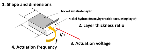
Figure 2-8. Parameters affecting actuation force of the actuator
1.Shape and dimension of the actuator influences frontal area A.
Since the coating current is proportional to actuator area (constant current density), we found that larger actuators contained many large pores mostly likely due to dissolution caused by over-current. The large pores reduces the strength of the actuator and decreases its effective actuation displacement. We thus identified through experiments that the maximum area which we could apply the coating conditions stated in the section "Fabrication" is 2 cm x 2 cm. Also, certain shapes are more effective in producing large end-tip displacement than others due to geometrical reasons. For example, rectangles with high aspect ratio are better than squares, circles, and triangles as illustrated in the figure below.

Figure 2-10. The tip velocity of 3 different actuators with different areas actuated in 1M NaOH at +/- 1.5V, 0.25 Hz

Figure 2-7. Proposed propulsion mechanism of the Nickel hydroxide/oxyhydroxide actuators
Video 1
When considering the magnitude of drag-based propulsive force, it is necessary to take both tip velocity and actuator area into consideration. We thus designed an experimental rig, where the actuators are connected to thin, aluminum strips (which conducts electricity) hung from the above, and the maximum horizontal displacement of the aluminum strip as a result of actuation will be the measure of actuation force.
Quantitative evaluation of the actuator's thrust is although not necessary but is benefitial to the robot design. According to Newton's second law
Net force = n x (Actuation force per actuator) - (body drag) = F = ma
The mass of the robot and the body drag can be readily estimated. We can then calculate the number actuators required to propel the body at specific acceleration values.
2. Drag-based approach for estimating actuation force
The actuation voltage is sensitive to various factors that have an influence on the electrochemistry in the electrochemical cell. For example, the actuation voltage range may change when a different reference electrode, counter electrode, or electrolyte is used.
Video 5
The underlying principle is that we assume the actuator can be modeled as a prismatic beam with a fixed end (clamped). The sum of all the forces acting on the beam (aluminum strip) would result in a net horizontal displacement at the tip, denoted by w, which can be related to the magnitude of total actuation force (subtracted by all resistance in liquid).
In order to translate the end deflection of aluminum strip into actuation force, a calibration test is needed. The aluminum strip will first be clamped horizontally, with a known weight attached at the mid-length causing a downward deflection. By noting down the downward deflections at different masses, we can establish a deflection-force relationship to calibrate for the end deflections measured in actuation tests.
Figure 2-17. The proposed measurement and force calibration setup
Due to time constraints, we were unable to complete the experiments to obtain a full set of analyzable data, but a video of the sample experimentation is shown below.
Video 6
