
Future work

Figure 6-1. Concepts for future work for Ni-Natare Project
1. Mass reduction of the robot
It is evident from the locomotion test that the current size and weight of the robot has to be further reduced in order to increase the velocity of motion. Several ways could be employed to reduce the weight of the robot.
First, consider eliminating weight of electronic components (~20%of total weight). For example, integrated circuit can be used to replace the current PCB board to reduce weight and space occupied, using wireless power transfer to eliminate battery (major weight contribution). While elimination of the battery weight is benefitial, it is equivalently important to reduce the power consumption of the actuation system; otherwise the size of the wireless transfer system will still appear bulky relative to the swimming robot. Harvard Microrobotics lab has done series of research on ultra-low mass, high efficiency power and control electronics, and details could be viewed from their research website.
Secondly, we can consider creative methods to reduce the weight of the robot's waterproof housing. For example, use readily purchased syringe as container for electronic components, or use tooth picks as chassis and food wraps and as water proof skin of the robot. Alternatively, smart composite microstructure fabrication offers self-folding, bendable robot chassis. For example, the body of an insect-like, ambulatory micro-robot designed by Harvard [3] has 8 degrees of freedom, consisted of alternating carbon fiber laminates and polymide thin films to create bendable, 3D articulated structure.
2. Better motion control
(i) Incorporating direction control and closed-loop feedback
At the current stage of the project, the robot's swimming direction cannot be controlled. It is propelled by 6 actuators receiving the same actuation voltages. It is possible to steer the robot by having a higher flapping frequency of actuators on one side of the robot. We have experimented that actuator's flapping rate can follow and be controlled by voltage scanning rate up to 4 Hz. Using the open-loop motion control, it might be possible to achieve different turning rate and turning radius of the robot by testing out different combinations of flapping frequencies on two sides of the robot. To take one step further, we should consider transforming open-loop motion control into closed-loop design by incorporating on-board sensors (such as accelerometers, gyroscopes, and cameras). These sensors can provide instantaneous feedback such as speed, location, and turning direction of the robot so that the motion of the robot can be adjusted accordingly. However, it should be noted that these components would add to additional weight of the robot.
(ii) Attempting different locomotion modes
The current propulsion purely relies on flapping (oscillation) of the actuators. It is also worthwhile to explore undulatory type of propulsion such as those of stingrays. (See Figure 6-1) This propulsion mode would require more than 5 actuators on each side of the robot, and the actuators would be actuated sequentially to form a sinusoidal waveform. For example, Harbin Institute of Technology has developed such a robotic ray [4] propelled by 10 actuators (5 on each side) made of Shape Memory Alloy wires embedded into elastic substrates.
Alternatively, it is possible to construct jet-type of propulsion by using star-shaped Nickel hydroxide/oxyhydroxide actuators. By attaching a thin plastic-film on top of the star actuator, the structure imitates the bell of a jellyfish. The video below shows actuation of a star-shaped nickel hydroxide/oxyhydroxide actuator at 2 Hz, which can be potentially turned into a design shown in Figure 6-3.
3. Optimization of the actuator
(i) Further increase the propulsive force by optimization of various parameters
To further increase the propulsive force of the actuator, the dimension and coating conditions of the actuator have to be further optimized for achieving large actuator area and high tip velocity. This process is attempted (see "Materials Characterization" page) but not thoroughly studied in this project.
(ii) Actuation in diversified mediums - NaOH packaging
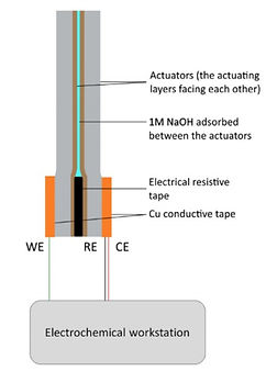
It has been demonstrated by the research of Kwan [5] that a self-contained actuation device can be constructed as shown in the figure below.
In this design, two actuators are first attached to separate pieces of Cu tape. An electrical resistive tape is then applied to separate the two Cu tape while holding the two actuators in close distance. Then, a polymer gel containing 1M NaOH is brushed on the inner face of both actuators to form the conductive path. One of the actuator is connected to the working electrode, which is the main actuator, while the other actuator merely served as a conductive electrode closing the circuit loop.
Under this configuration, the actuation is no longer confined in alkaline solution but can also actuate in water or in air. This expands the range of environment in which the actuators can be applied. The video above demonstrates the self-contained actuation device actuating in air at a slow rate.
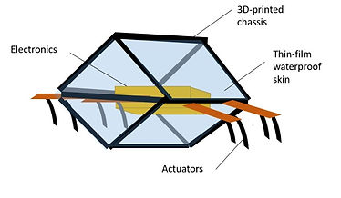
Figure 6-2. (i) Schematic of the concept robot and (ii) plastic food wrap

Figure 6-3. Schematic of jet-propelled robot using Nickel hydroxide/oxyhydroxide actuators
Figure 6-4. Schematic of self-contained actuator developed by Kwan [5]

Picture source:
The finished prototype is a 95mm x 78mm x 25mm floating, boat-shaped robot made from polystyrene foam. The device floats at the electrolyte's surface and is propelled by six 20mm x 4 mm nickel hydroxide/oxyhydroxide actuators, each actuated by alternating step voltages of +/-1.5V at frequency 0.167 Hz. The boat contained a battery and an infrared-receiver unit so that the motion could be remotely controlled within 10m distance. The best free locomotion test result was a 8 cm forward displacement accomplished within 15 minutes, with a maximum instantaneous velocity of 0.208 mm/s. The instantaneous acceleration of the boat indicated a net force of 0.13 uN acting on it calculated from the Newton's second law. Through experiments, the propelling force of the actuators were estimated in range of micro-Newtons.
Summary of our work
Our work integrates knowledge from material science, underwater propulsion mechanics, fundamental electrical engineering, and various hands-on DIY skills. The project started from understanding and fabricating the Nickel hydroxide/oxyhydroxide actuator, to the development of the remote controlled circuit and suitable robot body shape and material. The final stage of this project involved a free locomotion test and the analysis of its results.
Future prospects
In fact, using artificial muscles as underwater propellers is not a new idea. Traditional underwater robots are usually driven by motor-based robotic joints to reproduce flapping or undulation motion of sea creatures. Lately, scientists began to conduct studies on replacing motor-driven actuators with artificial muscles since they are more compact, and in some cases more energy-saving. The first video on the left shows a biomimetic robotic ray propelled by an IPMC actuator jointly developed by The University of Tartu and Tallinn University of Technology. The second video on the left shows IPMC used as oscillatory fish tail developed at The University of Nevada.
A review: Underwater robots using smart actuators
Where are we now?
In the following, a comparison between our final prototype and other underwater robots using smart actuators included in the work by Chu et. al [1] will be presented. The limitations of our robot, the causes of these limitations, and possible solutions for improvements would be briefly addressed.
The first thing the team noticed is that our actuator’s propulsion capability is still highly limited and have to be improved via several means. Underwater robots using smart actuators as propellers with a length similar to our work (~100mm, or 10 cm) typically achieved a speed of 0.1 ~ 0.5 body length/sec. In our current work, we only attained 0.0022 body length/sec. This large gap indicated the room for improvement. The reason for limited forward speed in our robot can be attributed to the low propelling frequency and the propulsion mode.
According to the classification by Chu et.al [1], our actuator propels with the body-caudal-fin actuation- oscillatory mode (BCA-O). Research indicated that the maximum attainable swimming speed of robot employing BCA-O mode is proportional to the flapping frequency of the propellers(s). Currently, our actuator can oscillate as fast as 25 Hz in the air, but the frequency is severely dampened to below 1 Hz under water/electrolyte. This thus reduces the achievable speed in our robot. Moreover, the typical achievable swimming speed for the robots operating at a low flapping frequency of 0.167 Hz (our current setting) and adopting BCA-O propulsion mode were at least capped at 0.1 BL/sec. However, our robot still have not yet achieved the speed of 0.1 BL/sec due to insufficient propelling force. Also, the propulsive force of each nickel hydroxide/oxyhydroxide actuator could generate was limited, estimated at the range of micro-Newtons. This implies that a large number of actuators would be required to propel a centimeter-sized robot body.
Regarding these two issues, a possible solution is to increase the actuation frequency to enhance the robot’s speed performance. However, our project discovered that an increased actuation frequency was complimented by reduced deformation in the actuator, which is also found in other types of artificial muscles. [2] Further research is required to identify the conditions for the actuator to flap at a higher frequency without compromising the bending amplitude. The second solution may be to reduce the size of the robot by more than half (<5 cm). This would reduce the mass needed to be accelerated and also the surface tension acting on the robot’s body, making propulsion easier for the actuators. Finally, measures to increase the propulsive force per actuator should be explored. This is discussed in the page of “Material Characterization”.
Another direction for resolving the low swimming speed in our robot may be changing the propulsion mode from BCA-O to jet propulsion, common in jelly fish. Chu et. al [1] found that underwater robots adopting jet propulsion mode can achieve much higher speed per body length at an actuation frequency below 1 Hz. This finding is advantageous for our robot since the large deformation of the nickel hydroxide/oxyhydroxide actuator is only preserved at low frequencies under 1 Hz. Chu [1] suggested that is even possible to achieve higher speed with lower actuation frequencies by using jet propulsion compared with BCA-O propulsion. Rapid, powerful strokes with large degrees of deformation are required in jet propulsion. Nickel hydroxide/oxyhydroxide actuator is suitable in this respect since it generates a relatively high actuation stress (in the order of several tens of MPa) and large end-deflection.
Finally, we should acknowledge the fact that existing underwater robots using artificial muscles are inferior to those using electric motors in terms of speed. On top of this, underwater swimming organisms swim faster than biomimicking robots, both motor-driven and artificial muscle-driven ones. Although conventional actuators such as electric motors have an advantage in power and rotational speed over artificial muscles, the latter is more compact and versatile and can therefore mimic more types of propulsion mechanisms. For example, jet propulsion was only reported to be achieved with artificial muscles but not electric motors [1]. Finally, there is room for all underwater robots to be improved in the aspect of speed when compared to their biological counterparts. We must admit that biological muscles are still by far one of the most powerful actuators in the nature, possessing large strain (>40%), fast strain response (>50%/s), high energy efficiency (~40%), and excellent durability at the same time. [2]
Source: Kam K. Leang, the Electroactive Systems and Controls Lab (easyLab) at the University of Nevada
Source:
http://www.youtube.com/watch?v=ccaJKascw8E
Original publication:
Punning, A.; Anton, M.; Kruusmaa, M.; Aabloo, A. 2004. A Biologically Inspired Ray-like Underwater Robot with Electroactive Polymer Pectoral Fins. IEEE Confrence "Mechatronics and Robotics 2004, 2:241 - 245.
References:
[1] Chu WS, Lee KT, Song SH, Han MW, Lee JY, Kim HS, Kim MS, Park YJ, Cho KJ, and Ahn SH. 2012. Review of Biomimetic Underwater Robots UsingSmart Actuators. International Journal of Precision Engineering And Manufacturing. 13(7) :1281-1292
[2] McGovern ST, Spinks GM, Xi B, Alici G, Truong V, Wallace GG. 2008. Fast bender actuators for fish-like aquatic robots. Proc. of SPIE, 6927: 69271L-1 - 12
[3] Gafford, Joshua B. ; Kesner, Samuel B. ; Wood, Robert J. ; Walsh, Conor J. 2013.
2013 IEEE/RSJ International Conference on Intelligent Robots and Systems, Nov: 2552-2558
[4] Wang, Z., Hang, G., Wang, Y., Li, J., and Du, W. 2008.“Embedded SMA wire actuated biomimetic fin: a module for biomimetic underwater propulsion,” Smart Materials and Structures, 17, Paper No. 025039
[5] Kwan KW, Hau NY, Feng SP, Ngan HW. 2017. Electrochemical actuation of nickel hydroxide/oxyhydroxide at sub-volt voltages. Sensors and Actuators B, 248:657–664